
Gear Train Design (Introduction to Engineering Design)
Overview & Abstract
In my Introduction to Engineering Design Course, I worked on team of 8 student to design the transmission for a commercial-turbofan accessory-drive gearbox, beginning with the input drive shaft rotating at 8 400 rpm with 750 in·lbf of torque and finishing with four correctly-timed output accessory shafts.
Objective
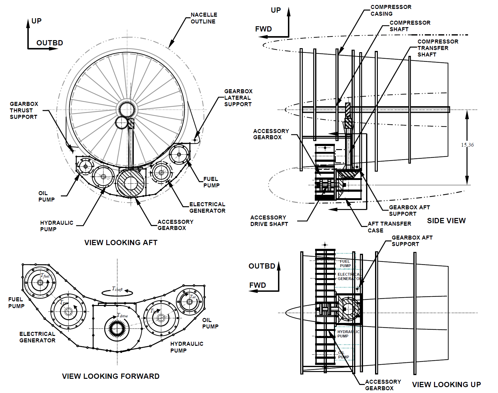
An accessory drive gearbox for a commercial aircraft is designed to fit below the jet engine compressor case. The gearbox is driven off the engine compressor shaft and drives the engine fuel pump, the engine oil pump, the hydraulic pump and the electrical generator, and is attached to the engine by three machined aluminum fittings (thrust, lateral, and aft support fittings) that are bolted to the gearbox housing.
The gearbox is driven by an accessory drive shaft that receives power from engine compressor spool through a compressor power transfer shaft. The compressor transfer shaft is connected to the accessory drive shaft through a bevel gear at the aft transfer case. The compressor transfer shaft is driven by the engine compressor at a speed of 12000 rev/min (ccw) and a torque of 525.2 ± 0.5 in·lbf , and the accessory drive shaft delivers a torque of 750.3 ± 0.5 in·lbf at a speed of 8400 rev/min (ccw). Direction of rotation as viewed from front of gearbox looking aft and looking down on gearbox. Assume that the input torque is equally divided between the two sides of the gearbox. The gearbox housing has a structural weight of 85 lbf without the gear train components or accessories installed. The accessory gear box shall meet the specified package dimensions and shall weigh no more than 260 lbf with accessories and gear train components installed. The bevel gear on the transfer shaft has 28 teeth with a pitch diameter of 3.5 inches, and the bevel gear on the accessory drive shaft has 40 teeth and a pitch diameter of 5 inches.
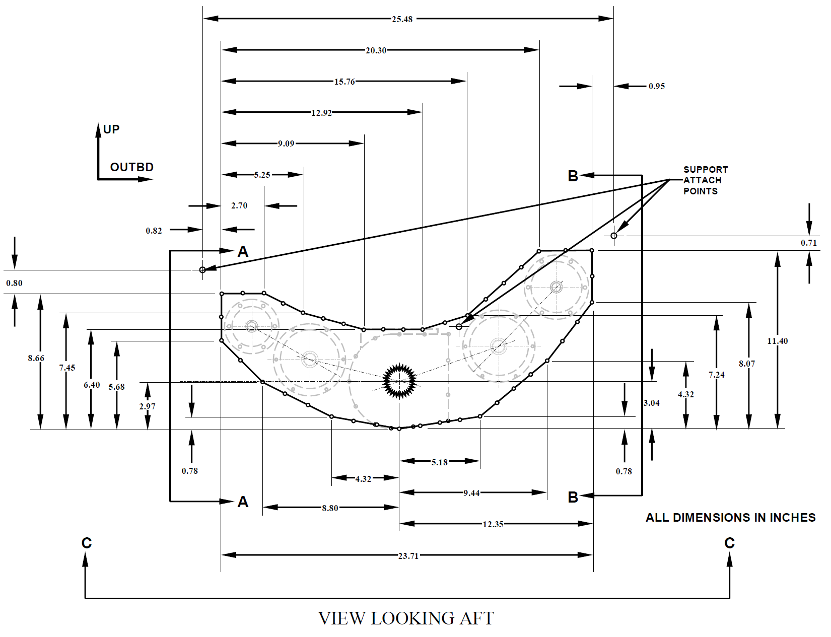
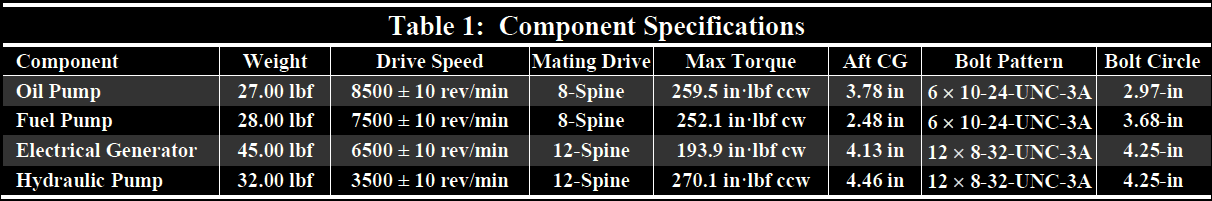
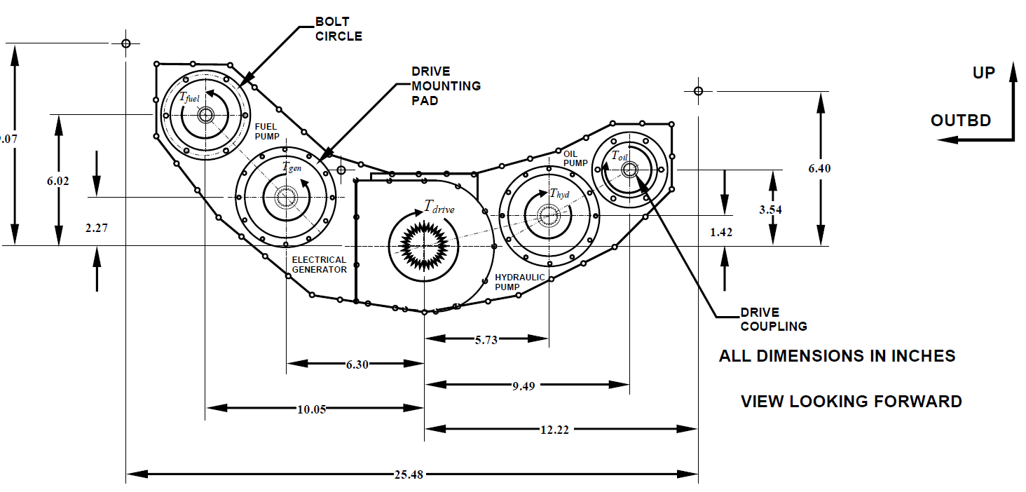
The individual accessories are mounted to the aft face of the housing and are driven at the speeds specified in Table 1, and their respective CG locations measured from the aft face of the accessory gearbox case are also listed. Each component is mounted using the specified number of fasteners. A front view of the geometry of the gearbox housing is shown.
The accessory drive housing supports the weight of the gearbox components. The details of the various components are listed in Table 1.
The locations of the accessory drive pads are shown in the figure below:
The following assumptions and additional spec requirements were included in the final design
Either spur or helical teeth; pressure angle shall be 20°
Uncrowned teeth
A No 10 quality standard for all gears
A reliability of 98%
Commercial enclosed units
Gearing to be adjusted at assembly of accessory gearbox
Loading is moderate shock, power is uniform
Operating temperature is below 250°F
The minimum required service life is equivalent to 10^(8) cycles for all gear train components
Geartrain Design and Layout
Gear Design and Loading
Bending Stress
Contact Stress
Shaft Analysis Sizing, and Geomtry
Shaft Loading for Accessory Drives
Conclusion
We applied the DE-ASME Elliptic criterion at all shaft discontinuities. The main drive-shaft’s retaining ring groove proved critical at a 1.66 design factor, while its keyway held 1.99; the tightest accessory shaft (Shaft D) showed 2.35, all above the 1.15 / 1.10 requirements, and an S-N curve confirmed the shaft operates in the infinite-life regime. Below is the DE-ASME Elliptic criterion equation used to calculate the FoS of the shaft.
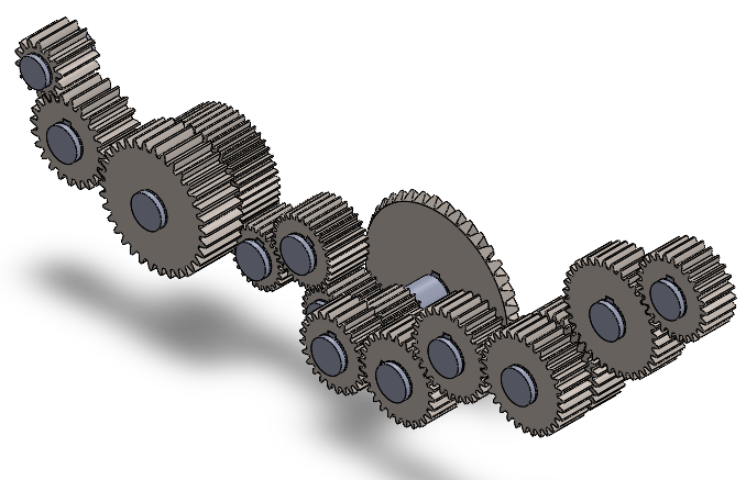
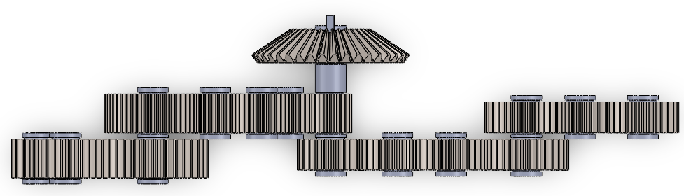
The final layout packs a 16 gear transmission, 15 of which are spur gears, plus a bevel gear which drives the input drive shaft from the outside of the gearbox from the turbofan input. The gearbox has a complex u shaped geometry that is 4.75 inches in depth (see below).
There are three compounded stages, mixed diametral pitches (10, 12 and 16 teeth · in⁻¹) and 20° spur teeth let every accessory hit its spec speed within ±10 rpm.
All the gears are made of Nitralloy 135M,chosen for its high nitrided hardness, but are of different grades: two drive trains are Grade 1, one is Grade 2, and one is Grade 3.
The shafts are made of 1.0 in-OD AISI 1050 steel, quenched & tempered at 400 °F, which provides the strength needed without exotic alloys. Using AGMA 2001 bending and contact formulas we verified that every gear cleared the project minimum safety factors (1.30 in bending, 1.15 in contact). The governing part is Gear 9, a 20-tooth, 1.25 in pitch-diameter pinion that accepts the full 375 in·lbf half-shaft torque, yet it still retains safety factors of 1.36 (bending) and 3.07 (pitting); a roughly 9 % torque increase would make it the first element to dip below margin. The table below shows the FoS in contact/pitting and bending stress for each gear.
Final Design
Factors of Saftey
All of our gears and shafts come out to 249.7 lbf, comfortably beneath the 260 lbf limit.
Analysis loops were automated in Excel, and the finished SolidWorks assembly meets AGMA Quality 10, 99 % reliability, and 10⁸-cycle life targets while identifying Gear 9 and the groove as the true growth-limiters for any future power surges.