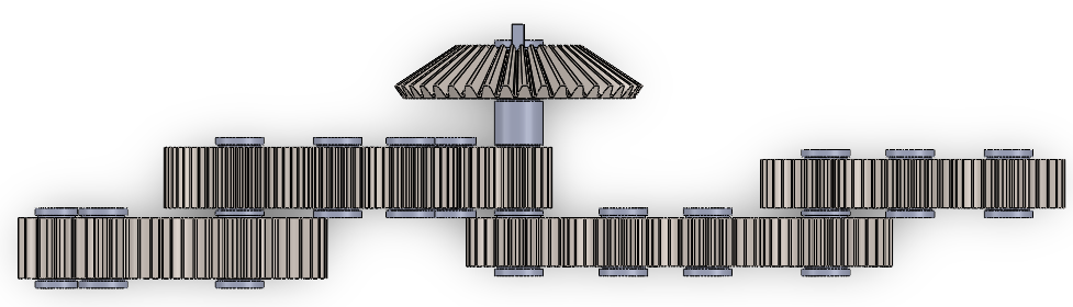
In my Introduction to Engineering Design Course, I worked on team of 8 student to design the transmission for a commercial-turbofan accessory-drive gearbox, beginning with the input drive shaft rotating at 8 400 rpm with 750 in·lbf of torque and finishing with four correctly-timed output accessory shafts.
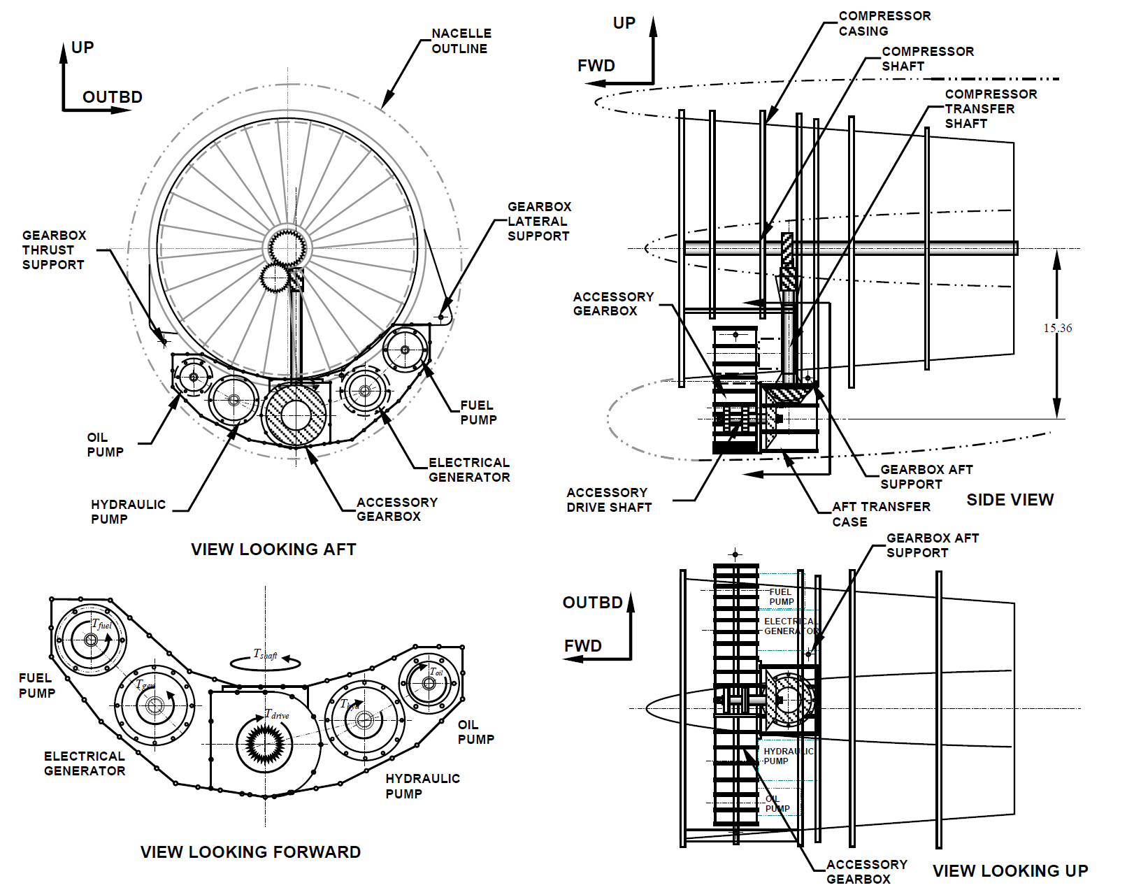
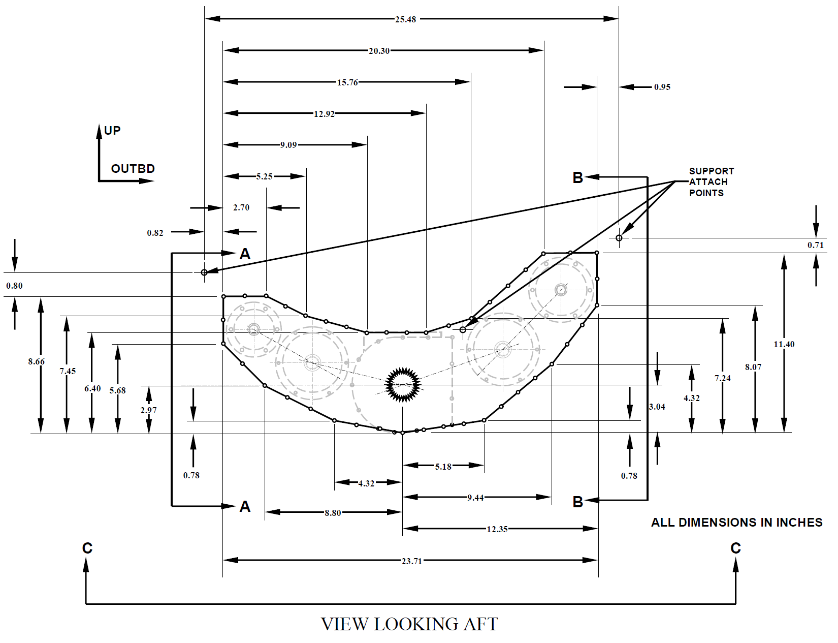
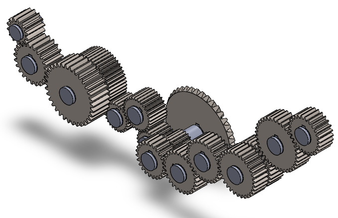
The final layout packs a 16 gear transmission, 15 of which are spur gears, plus a bevel gear which drives the input drive shaft from the outside of the gearbox from the turbofan input. The gearbox has a complex u shaped geometry that is 4.75 inches in depth (see below).
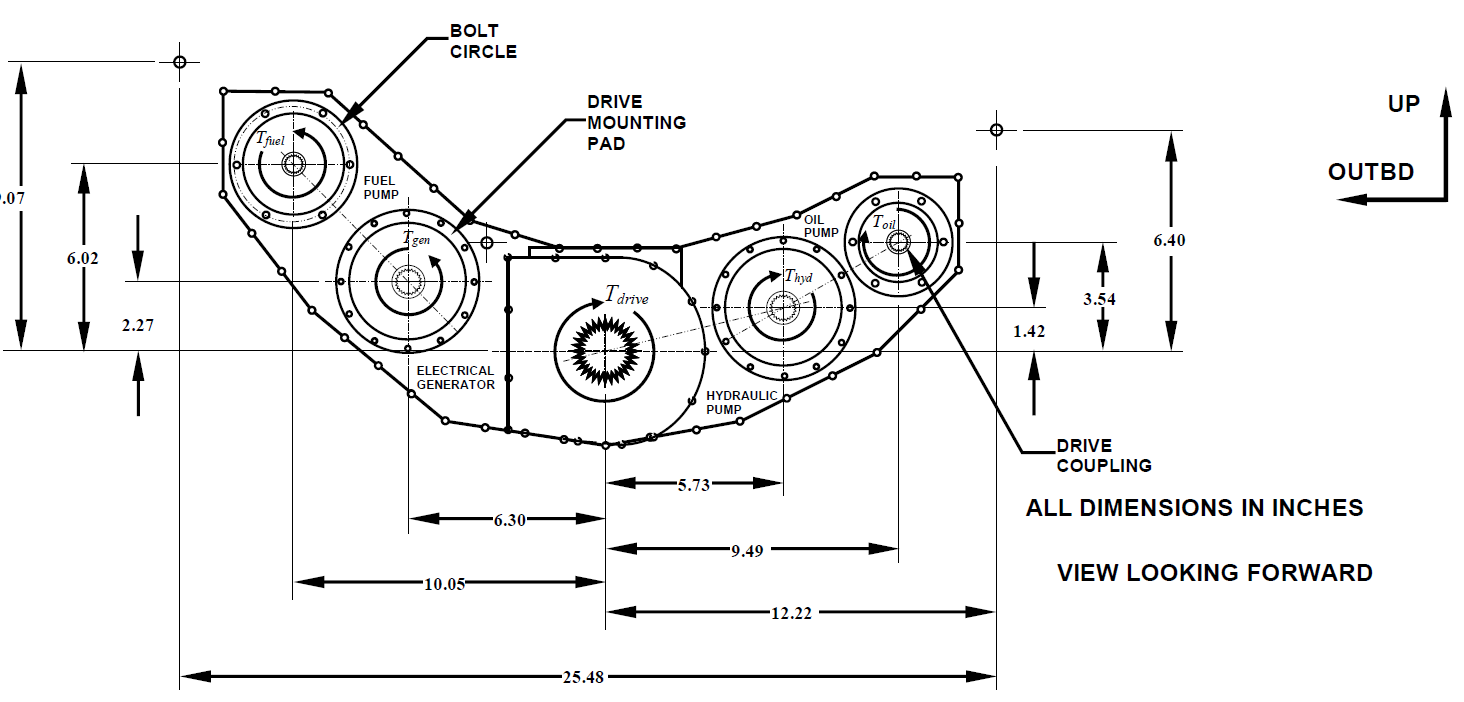
There are three compounded stages, mixed diametral pitches (10, 12 and 16 teeth · in⁻¹) and 20° spur teeth let every accessory hit its spec speed within ±10 rpm.
All the gears are made of Nitralloy 135M,chosen for its high nitrided hardness, but are of different grades: two drive trains are Grade 1, one is Grade 2, and one is Grade 3.
The shafts are made of 1.0 in-OD AISI 1050 steel, quenched & tempered at 400 °F, which provides the strength needed without exotic alloys. Using AGMA 2001 bending and contact formulas we verified that every gear cleared the project minimum safety factors (1.30 in bending, 1.15 in contact). The governing part is Gear 9, a 20-tooth, 1.25 in pitch-diameter pinion that accepts the full 375 in·lbf half-shaft torque, yet it still retains safety factors of 1.36 (bending) and 3.07 (pitting); a roughly 9 % torque increase would make it the first element to dip below margin. The table below shows the FoS in contact/pitting and bending stress for each gear.
We applied the DE-ASME Elliptic criterion at all shaft discontinuities. The main drive-shaft’s retaining ring groove proved critical at a 1.66 design factor, while its keyway held 1.99; the tightest accessory shaft (Shaft D) showed 2.35, all above the 1.15 / 1.10 requirements, and an S-N curve confirmed the shaft operates in the infinite-life regime. Below is the DE-ASME Elliptic criterion equation used to calculate the FoS of the shaft. The table below goes on for quiet a while, be prepared to scroll.
Since this gearbox is going on a plane, there is a strict weight limit of 260 lbf. All of our gears and shafts come out to 249.7 lbf, comfortably beneath the 260 lbf limit.
Analysis loops were automated in Excel, and the finished SolidWorks assembly meets AGMA Quality 10, 99 % reliability, and 10⁸-cycle life targets while identifying Gear 9 and the groove as the true growth-limiters for any future power surges.
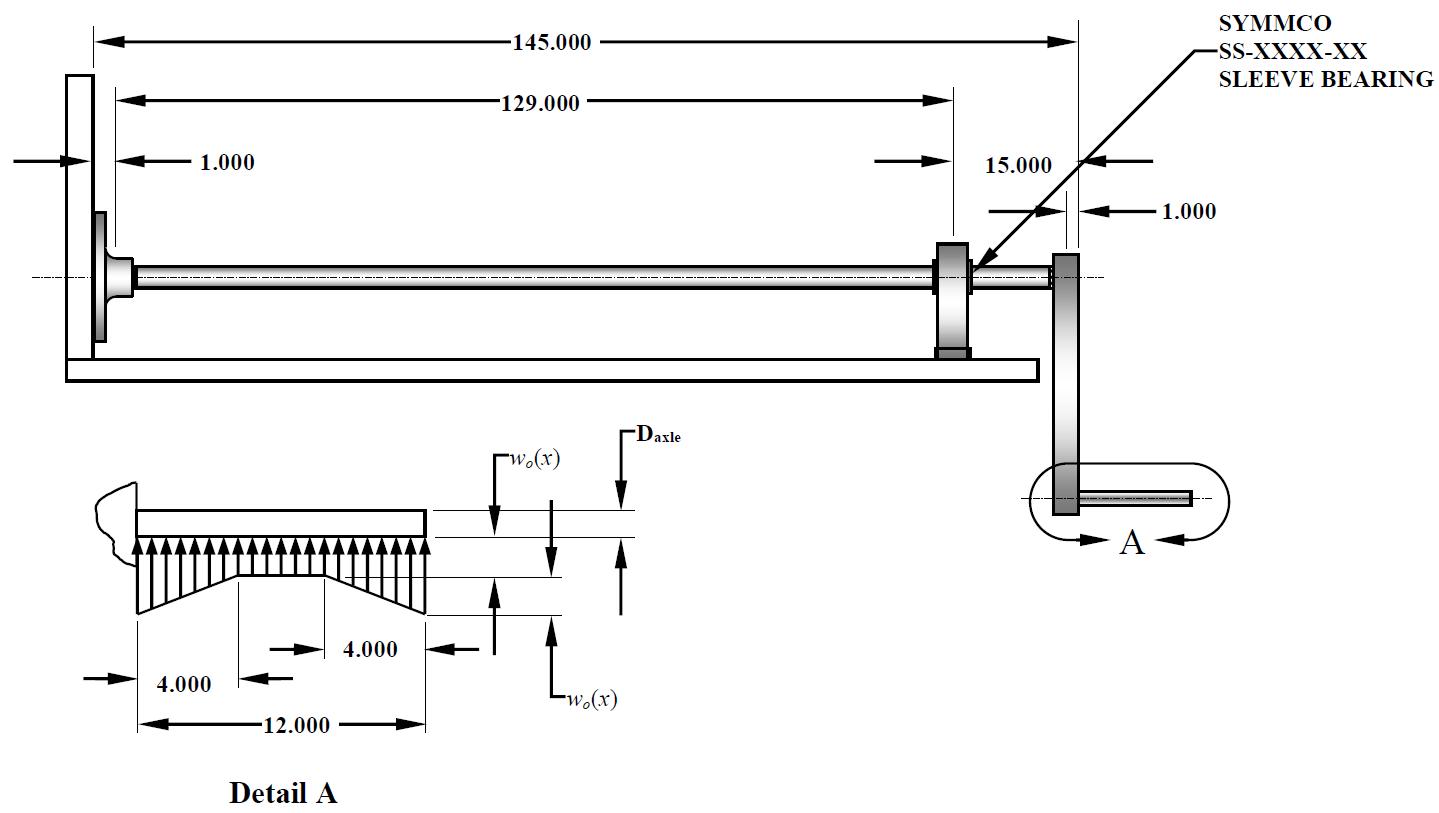
In my Introduction to Engineering Design course I completed a solo design of a torsion bar suspension shaft and all associated hardware for a theoretical heavy duty vehicle. Below is the full completed assembly of the torsion bar along with the nomenclature that will be used to reference each portion.
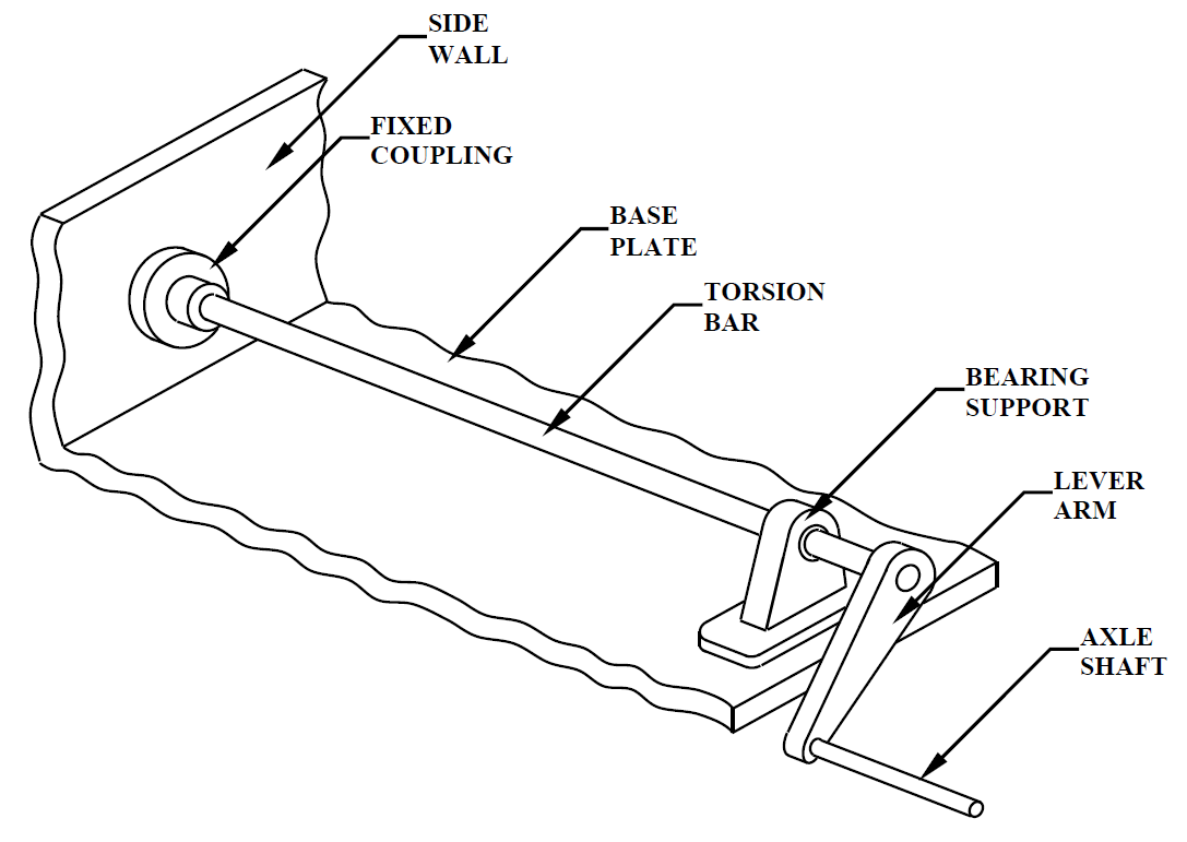
The side wall and base plate are made of an unspecified aluminium alloy, with the base being 0.4375 inches thick, and the side wall being 0.250 inches thick. The material and thickness of the base plate and side wall were out of the scope of this project and were intentionally vaguely defined in the project briefing.
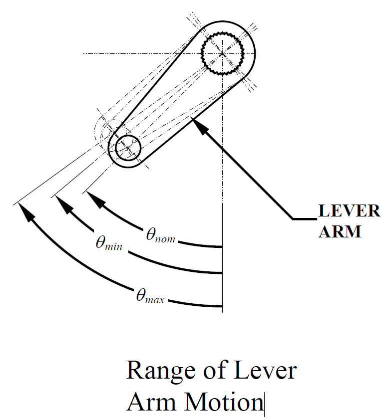
The torsion bar is made of hollow 4130 Q&T 205°C/400°F steel with a 2.15 inch inner and 2.673 inch outer diameter. The torsion bar was dimensioned so when the bar is at the maximum operating deflection angle, (51°) it is supporting 2510 lbf, and when at its minimum operating deflection angle (47°) it is supporting 890 lbf, enough to handle bumps and hauling heavy loads. At no load, the lever arm sits at 45°.
The torsion bar came out with a static torsional safety factor of 10.4 and a fatigue safety factor of 2.7 (Modified Goodman, 99.9 % reliability), which places the component in the infinite-life region of the S-N curve.

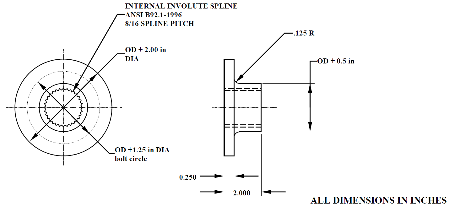
Both ends of the bar were keyed with a 20-tooth, 30° pressure angle 8/16 spline that transmits up to 29 k lbf-in from the lever arm to the fixed coupling without slip. ANSI-B92 checks yielded safety factors of 38.9 in compression, 1.06 in shear, and 1.73 in the spline shaft, clearing the 1.05 requirement while keeping the bar diameter in spec.
I dimensioned the aluminum bearing support lug made of 3003-H16 (0.50 in thick) with a bronze sleeve bearing that mounts the bar to the chassis. The lug records a FoS of 4.16 and the bearing interface posts 7.3 (R/D) / 31.5 (W/D)—both well above the mandated 3.75. Two SAE-Grade-2 bolts clamp the lug and the joint analysis returned safety factors of 1.21 in yield, 3.33 in overload, and 4.46 against separation.

To complete the linkage I sized a 12 in solid 1010 cold drawn steel axle to 2.5 in Ø, delivering a bending safety factor of 2.24 versus the 1.15 minimum and 0.79 in of vertical wheel travel. A minimum shaft diameter of 2.01 was required to meet the FoS, but for each of manufacturing and additional safety it was increased to a 2.5 inch diameter shaft.
All calculations (static torsion, fatigue, spline contact, bolt stiffness, lug bearing, axle bending) were automated in Excel. The result is a cost efficient and manufacturable suspension member whose weakest points, which is the spline shear and bolt yield, still hold more than 5% margin above every project criterion.
This is a placeholder.
This is a placeholder.
This is a placeholder.
This is a placeholder.
This is a placeholder.
This is a placeholder.
This is a placeholder.